Scope of This Guide
This guide describes the heated tool butt welding procedure for polypropylene (PP) as specified in DVS 2207-11 (English translation of the German August 2008 edition, December 2008). DVS 2207-11 covers PP pipes, piping parts, fittings, and panels. This guide focuses on the application to PP panels. The procedure applies to PP-H (homopolymer), PP-B (block copolymer), and PP-R (random copolymer).
Edition disclaimer: This article is based on the supplied December 2008 English translation of DVS 2207-11. Users must verify whether a newer edition or project-specific requirement applies before relying on the values and procedures described here.
Quantitative values presented here come from DVS 2207-11 Tables 1 and 2. Procedural requirements come from Sections 3 and 4 of the standard. Heating-up times, changeover times, pressure build-up times, and cooling times are taken from Table 2; gap tolerances are taken from Table 1. Intermediate thicknesses must be interpolated. The table applies at approximately 20 degrees C outdoor temperature with moderate air movement.
According to the supplied edition, the procedure may generally be assumed suitable for PP materials with an MFR 190/5 of 0.4 to 1.0 g/10 min, approximately corresponding to an MFR 230/2.16 of 0.2 to 0.6 g/10 min. Materials outside this range require separate proof of weldability.
Table 2 covers panels up to 50 mm thickness. Do not extrapolate beyond 50 mm based on Table 2.
Welding Flow per DVS 2207-11
- 1. Clean the joint surfaces before machining where necessary, using a cleaning agent that fully evaporates and complies with applicable requirements.
- 2. Machine the joining faces immediately before welding. Do not touch the machined surfaces. Remove chips without contacting the faces.
- 3. Align the sheets. Apply alignment pressure (0.10 N/mm squared) until the required alignment bead is formed.
- 4. Reduce pressure to less than or equal to 0.01 N/mm squared (heating-up pressure). Heat for the time specified in DVS Table 2.
- 5. Remove the heating plate quickly. Changeover time per DVS Table 2; keep as short as possible.
- 6. Build up joining pressure (0.10 plus or minus 0.01 N/mm squared) within the pressure build-up time specified in DVS Table 2.
- 7. Cool under pressure for the duration specified in DVS Table 2. Mechanical loading is only permitted after complete cooling. For workshop welding of panels 15 mm and thicker, cooling under pressure may be shortened by up to 50 percent if only slight loading occurs during removal and storage. Full mechanical loading remains prohibited until complete cooling.
- 8. Inspect the weld per DVS 2202-1.
All quantitative values are in the parameter tables below.
Equipment Required
Primary Equipment
| Equipment | DVS 2207-11 Requirements |
|---|
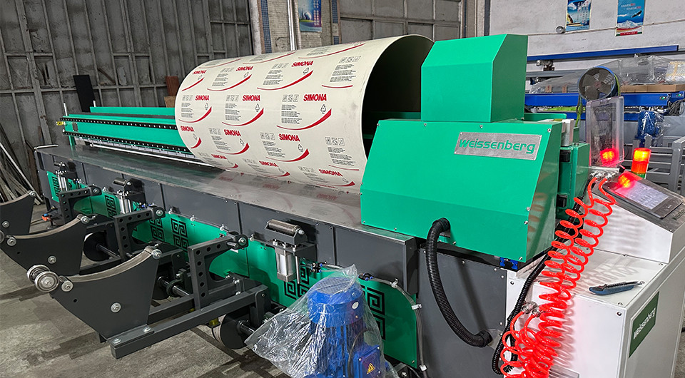
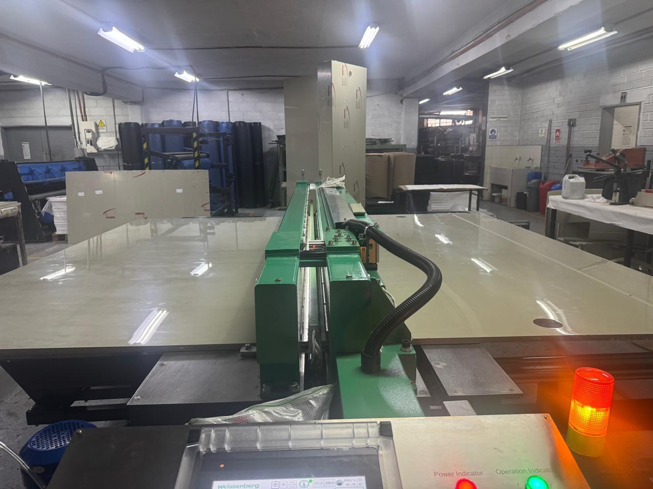
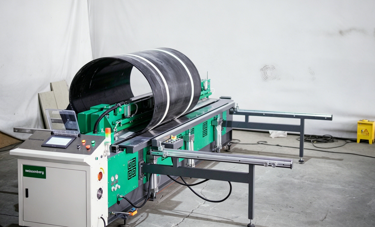
| Heated tool butt welding machine | Must provide controlled pressure stages (alignment, heating, joining). Required heated-tool surface temperature: 210 plus or minus 10 degrees C |
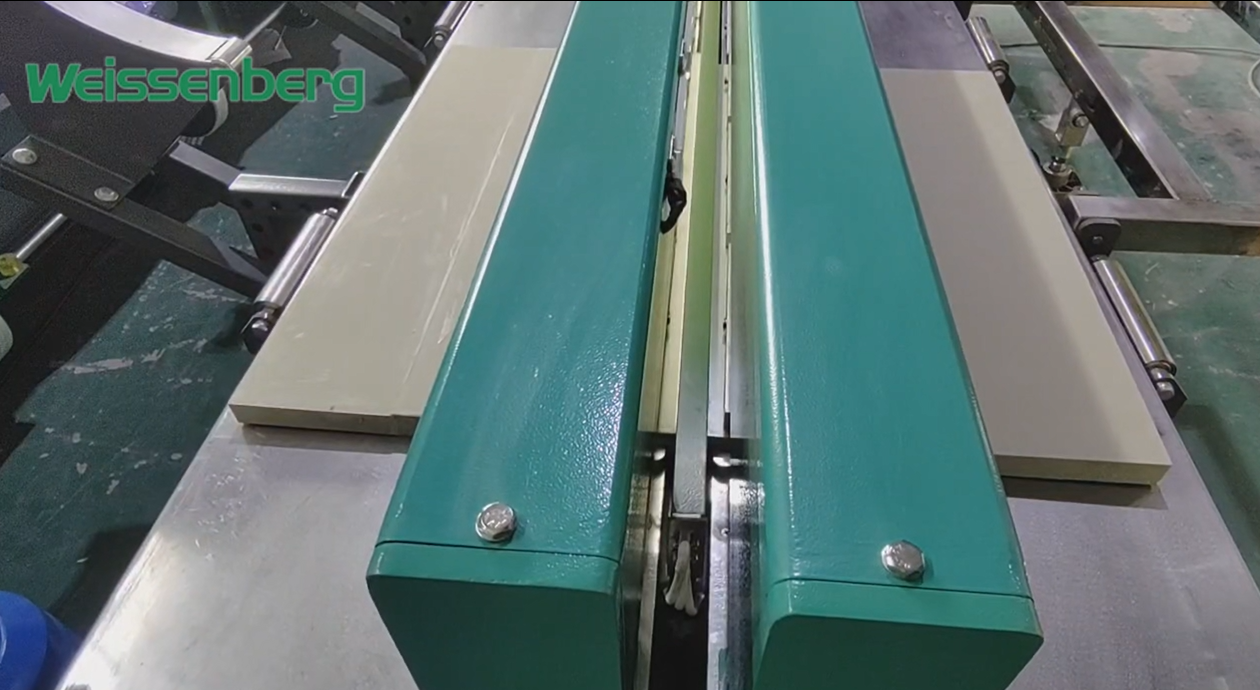
| Heating tool | Surface temperature: 210 plus or minus 10 degrees C. Must have an undamaged anti-adhesive coating or covering. Tool surface must be clean before every weld |
| Clamping system | Upper and lower clamps; capable of holding panels within gap tolerances (DVS Table 1) |
| Edge planer / facing tool | For machining joining faces immediately before welding |
Personnel and Process Qualification
- Welding should be performed by trained and appropriately qualified personnel. Panel heated tool butt welding qualification follows DVS 2212-1.
- Machines and jigs should meet the applicable requirements of DVS 2208-1.
- Trial welds should be produced and tested under the actual working conditions before and, where required, during production welding.
- Welding process data should be recorded for each production weld.
DVS Table 1: Maximum Permitted Gap (Panels)
| Panel Width (mm) | Maximum Permitted Gap (mm) |
|---|
| Less than or equal to 1500 | 1.0 |
| 1500 to 2000 | 1.3 |
| 2000 to 2300 | 1.5 |
| 2300 to 3000 | 2.0 |
Maximum Permitted Misalignment
The misalignment between the joining faces must not exceed 0.1 times the panel thickness. Greater misalignment can reduce the load-bearing capacity of the welded joint. This requirement applies in addition to the gap tolerances in Table 1.
Supporting Tools
- Cleaning agent: must fully evaporate and comply with applicable requirements. Use lint-free, undyed paper.
- Surface temperature probe: to verify heated tool surface temperature
- Feeler gauge: to verify gap tolerances per DVS Table 1
- Stopwatch: to verify heating-up, changeover, pressure build-up, and cooling times
- Thickness gauge: for panel thickness verification
Preparation and Cleaning per DVS 2207-11
Workpiece Conditions
- • The welding area should be protected from wind and moisture.
- • The workpieces must be at the same temperature. Avoid uneven heating caused by direct sunlight.
Cleaning and Machining
- • Clean the joint surfaces before machining where necessary, using a cleaning agent that fully evaporates and complies with applicable requirements. Use lint-free, undyed paper.
- • Machine the joining faces immediately before welding. Do not machine faces and then wait.
- • Remove chips without touching the faces.
- • Do not routinely clean freshly machined faces. They should be welded clean. Only clean again if they have subsequently been contaminated.
- • Do not touch the machined surfaces by hand.
Note on cleaning agents: DVS 2207-11 requires a cleaning agent with complete evaporation and gives a mixture of 99 parts high-purity ethanol (99.8 percent purity) and one part MEK as an example. Cleaning agents tested according to DVGW VP 603 also satisfy this requirement. Use lint-free, undyed paper.
Step-by-Step Welding Procedure
1. Alignment
Clamp the panels. Verify the gap between joining faces is within DVS Table 1 tolerances. Check misalignment: less than or equal to 0.1 times the panel thickness. Apply alignment pressure: 0.10 N/mm squared. Form the required alignment bead. Alignment bead dimensions per DVS Table 2. The alignment bead confirms even contact across the joining faces.
2. Heating-Up
Insert the heated tool (temperature: 210 plus or minus 10 degrees C) between the joining faces. The heated tool should only be used at least ten minutes after reaching the nominal temperature so that thermal equilibrium can occur. Reduce pressure to less than or equal to 0.01 N/mm squared (heating-up pressure). Hold for the heating-up time specified in DVS Table 2.
3. Changeover
Remove the heating plate quickly. Changeover time must follow DVS Table 2 and be kept as short as possible.
4. Joining
Build up joining pressure: 0.10 plus or minus 0.01 N/mm squared within the pressure build-up time specified in DVS Table 2. A uniform double bead should be formed on both sides. Some asymmetry may occur due to different flow behaviour of the two panel edges. The minimum bead dimension K must remain greater than zero.
5. Cooling
Maintain joining pressure throughout the cooling period specified in DVS Table 2. Mechanical loading is only permitted after complete cooling. Conditional allowance: for workshop welding of panels with wall thickness 15 mm or greater, the cooling time under pressure may be shortened by up to 50 percent, provided only slight loading occurs during removal and storage. Full mechanical loading remains prohibited until complete cooling has been achieved.
General Process Values
| Parameter | Value |
|---|
| Heated-tool surface temperature | 210 plus or minus 10 degrees C |
| Alignment pressure | 0.10 N/mm squared |
| Heating-up pressure | Less than or equal to 0.01 N/mm squared |
| Joining pressure | 0.10 plus or minus 0.01 N/mm squared |
These process values are from DVS 2207-11. The heated tool should only be used at least ten minutes after reaching the nominal temperature so that thermal equilibrium can occur.
DVS 2207-11 Table 2 Guide Values for PP Panels
The following grouped guide values apply at approximately 20 degrees C outdoor temperature with moderate air movement. The alignment bead heights and cooling times are minimum values. The changeover times are maximum values. These are DVS guide values. Intermediate thicknesses must be interpolated, and any deviation should be validated through the applicable welding qualification procedure. Table 2 covers panels up to 50 mm. Do not extrapolate beyond 50 mm based on this table.
| Panel Thickness (mm) | Min. Alignment Bead Height at the Heated Tool (mm) | Heating-Up Time (s) | Max. Changeover (s) | Pressure Build-Up (s) | Min. Cooling (min) |
|---|
| up to 4.5 | 0.5 | up to 135 | 5 | 6 | 6 |
| above 4.5 to 7 | 0.5 | 135 to 175 | 5 to 6 | 6 to 7 | 6 to 12 |
| above 7 to 12 | 1.0 | 175 to 245 | 6 to 7 | 7 to 11 | 12 to 20 |
| above 12 to 19 | 1.0 | 245 to 330 | 7 to 9 | 11 to 17 | 20 to 30 |
| above 19 to 26 | 1.5 | 330 to 400 | 9 to 11 | 17 to 22 | 30 to 40 |
| above 26 to 37 | 2.0 | 400 to 485 | 11 to 14 | 22 to 32 | 40 to 55 |
| above 37 to 50 | 2.5 | 485 to 560 | 14 to 17 | 32 to 43 | 55 to 70 |
Source: DVS 2207-11 Table 2 (December 2008 English edition). The alignment bead heights and cooling times are minimum values, while the changeover times are maximum values. These are DVS guide values. Intermediate thicknesses must be interpolated, and any deviation should be validated through the applicable welding qualification procedure. Guide values assume approximately 20 degrees C ambient temperature with moderate air movement.
Practical Post-Weld Inspection Guidance
The following inspection checklist is intended as practical guidance. Formal acceptance should follow the applicable edition of DVS 2202-1. Visual inspection should verify:
- Uniform double bead visible on both sides. Some asymmetry may occur due to different flow behaviour. K must remain greater than zero.
- Correct alignment. No step or height mismatch across the weld line.
- No contamination. No embedded foreign particles.
- No cracks. No visible cracks in the bead or heat-affected zone.
- No voids. No bubbles or cavities.
- No discoloration. Weld zone colour should match the base material.
Troubleshooting (Practical Engineering Guidance)
| Observation | Likely Cause | Suggested Check |
|---|
| No double bead (incomplete fusion) | Changeover exceeded Table 2 maximum; heating-up time insufficient | Verify changeover with stopwatch; confirm heating-up time within range |
| Bead asymmetry with K equals 0 on one side | Uneven pressure distribution; panels not parallel | Re-check clamp alignment; verify DVS Table 1 gap |
| Excessive melt expulsion | Heating-up pressure exceeded 0.01 N/mm squared | Verify heating-up pressure setting |
| Voids or bubbles | Moisture in material; contamination | Check cleaning and storage conditions |
| Discoloration (yellowing or browning) | Tool temperature exceeded 220 degrees C | Verify surface probe; maintain 210 plus or minus 10 degrees C |
Best Practices for DVS-Compliant Welding
- Machine joining faces immediately before welding. Do not machine and then delay welding.
- Never touch machined surfaces by hand.
- Do not routinely clean freshly machined faces. Weld them clean. Clean again only if subsequently contaminated.
- Protect the welding area from wind, moisture, and direct sunlight.
- Clean the heated tool surface before every weld. Use lint-free, undyed paper.
- The heating tool must have an undamaged anti-adhesive coating or covering. Inspect before each weld.
- Express welding pressure in N/mm squared (specific pressure), not bar. Bar depends on cylinder area. Convert using your machine manufacturer data.
- Record all parameters per weld for traceability: panel thickness, heating-up time, changeover time, joining pressure, cooling time, tool temperature.
DVS 2207-11 Compliance Checklist
Pre-Weld
| Check | Item |
|---|
| Welding area protected from wind and moisture |
| Workpieces at same temperature; no direct sunlight on joining faces |
| Cleaning performed before machining where necessary, with fully evaporating approved agent |
| Joining faces machined immediately before welding |
| Chips removed without touching faces |
| Freshly machined faces not routinely cleaned (only if subsequently contaminated) |
| Machined surfaces not touched by hand |
| Heated tool surface temperature verified: 210 plus or minus 10 degrees C |
| Heated tool anti-adhesive coating undamaged; surface cleaned before this weld |
| Gap between clamped panels within DVS Table 1 tolerance |
| Panel misalignment checked: less than or equal to 0.1 times panel thickness |
During Weld
| Check | Item |
|---|
| Alignment pressure: 0.10 N/mm squared. Alignment bead formed per Table 2 dimension |
| Heating-up pressure reduced to less than or equal to 0.01 N/mm squared |
| Heating-up time within Table 2 range for this thickness group |
| Changeover time less than or equal to Table 2 maximum. Kept as short as possible |
| Joining pressure build-up within Table 2 time |
| Joining pressure: 0.10 plus or minus 0.01 N/mm squared |
| Cooling time greater than or equal to Table 2 minimum. Clamps not released early |
Post-Weld Inspection
| Check | Item |
|---|
| Uniform double bead visible on both sides. K greater than 0 |
| Correct alignment. No step or mismatch |
| No contamination, cracks, voids, or discoloration |
| Welding report generated with all recorded parameters |
FAQ
Why is heating-up pressure almost zero (less than or equal to 0.01 N/mm squared)?
Only light contact is needed for heat transfer. Higher pressure during heating would squeeze out the molten layer, reducing the melt volume available for fusion in the joining phase.
Why must changeover be completed so quickly?
The molten PP surface begins to cool immediately after leaving the heated tool, which can negatively affect weld quality. If the changeover exceeds the DVS Table 2 maximum, the surface temperature may drop below the fusion point, producing a cold weld.
Why should machined surfaces never be touched by hand?
Skin oils contaminate the fusion surface and prevent molecular bonding at the contamination site, creating a local weak point.
Why is welding pressure expressed in N/mm squared instead of bar?
Bar indicates machine gauge pressure and varies with cylinder configuration. Specific pressure (N/mm squared) is the correct process parameter because it accounts for the actual force per unit weld area. Consult your machine manufacturer for bar to N/mm squared conversion for your equipment.
Why must panels be protected from sunlight before welding?
Uneven heating from direct sunlight or local heat sources causes differential thermal expansion, which changes the gap between panels and makes alignment impossible to maintain.
Why are the DVS Table 2 values described as guide values?
DVS Table 2 provides guide values for an ambient temperature of approximately 20 degrees C with moderate air movement. However, the alignment bead heights and cooling times are minimum values, while the changeover times are maximum values. Trial welds should be produced and tested when actual working conditions differ significantly from the stated reference conditions.
What is the difference between DVS 2207-11 and DIN EN ISO 15013?
DVS 2207-11 concerns heated tool butt welding procedures and guide values for PP. DIN EN ISO 15013 concerns extruded PP panels, their requirements and test procedures. They address different subjects. One is a welding procedure standard, the other a material or product standard. They are not interchangeable alternatives.
Can cooling under pressure be shortened?
DVS 2207-11 includes a conditional allowance. For workshop welding of panels with wall thickness 15 mm or greater, the cooling time under pressure may be shortened by up to 50 percent, provided only slight loading occurs during removal and storage. Full mechanical loading remains prohibited until complete cooling has been achieved. For all other cases, follow the full cooling times in Table 2.
Key Takeaways
PP heated tool butt welding per DVS 2207-11 defines a procedure with three distinct pressure stages and grouped guide values for heating-up time, changeover time, pressure build-up time, and cooling time. The key parameters are:
- • Heated tool: 210 plus or minus 10 degrees C; undamaged anti-adhesive coating
- • Alignment pressure: 0.10 N/mm squared until required bead forms
- • Heating-up pressure: Less than or equal to 0.01 N/mm squared
- • Joining pressure: 0.10 plus or minus 0.01 N/mm squared, built up within Table 2 time
- • Cooling: Per Table 2. Conditional 50 percent reduction allowed for 15 mm and thicker workshop welds with slight loading only
This guide focuses on panel applications. For the complete standard, refer to the references below.
References
- • DVS 2207-11: Welding of Thermoplastics Heated Tool Welding of Polypropylene (PP) Pipes, Piping Parts, Fittings and Panels. English translation of the German August 2008 edition, December 2008.
- • DVS 2202-1: Imperfections in Thermoplastic Welded Joints Classification, Description, Assessment.
- • DVS 2212-1: Qualification Testing of Plastics Welders.
- • DVS 2208-1: Welding of Thermoplastics Machines and Devices for Heated Tool Welding of Pipes, Piping Parts and Panels.
- • DIN EN ISO 15013: Extruded Panels Made of Polypropylene (PP) Requirements and Test Procedures.